If you’re a connector molder or a design engineer sourcing connector tooling, you’ve probably heard the phrase “shot size” thrown around in mold quotes, technical walkthroughs, or part validation meetings—but it’s rarely explained in plain, practical terms. As someone who’s spent 12 years running a connector mold supplier, I’ve seen first-hand how miscalculating shot size doesn’t just lead to minor inefficiencies: it can cause short shots, material waste, mold wear, and even part failures that delay production for weeks. I’ve worked with teams that guessed shot size and ended up scrapping 30% of their raw material on every run, and others who ignored the rule and cracked a $50,000 mold core. Today, I’m breaking down how to calculate connector mold shot size properly, with context specific to connector applications, not generic molding. Connector Mold
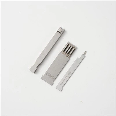
First, let’s start with what shot size actually is, for anyone who might be new to molding jargon. Shot size is the maximum volume of molten plastic an injection molding machine can inject into a mold in a single cycle. It’s measured in either cubic centimeters (cc) or ounces, depending on where your supplier is based. For connectors, this isn’t just a vague number from a machine spec sheet—it’s non-negotiable because connectors are almost always multi-cavity, small-part assemblies with tight tolerances. A typical USB Type-C connector, for example, is less than 1cc total part volume, but a 24-cavity mold for that same connector would have a total cavity volume of ~22cc, plus runners and gates that add another 3–5cc. If your shot size calculation only counts the part and forgets the runner system, you’ll almost always end up with a shot that’s too small, leading to short shots that leave half the cavities empty.
Why does this matter so much for connectors specifically? Connectors need zero flash (extra plastic on the edges) because flash can prevent proper mating, cause misalignment, or even break off during insertion. Flash happens when too much material is injected into a mold, or when a shot size is overestimated and you’re injecting more material than needed to fill all cavities and runners. On the flip side, a too-small shot size doesn’t fully fill the gates—leading to cold, brittle weld lines that cause connectors to fail pull-out tests, a critical spec for automotive or aerospace connectors. I had a customer last year who used a generic shot size calculator that only counted part volume, skipped runners, and ended up with 10% of their first production run failing pull tests. It took them two weeks to re-calculate, adjust the mold, and get back on track; they lost ~$80,000 in revenue because they rushed a miscalculation.
Now, let’s walk through the step-by-step calculation, with the numbers that matter for connectors, not just general molding. First, gather three core sets of data: 1) the volume of all molded parts in your cavity layout, 2) the volume of the runner system (sprue, primary runners, secondary runners, and gates) that feeds those cavities, and 3) a 10–15% buffer for material compression, machine dead volume, and minor variations in plastic viscosity.
Let’s break each part down with a real connector example, since that’s what we work with. Let’s say you’re designing a 16-cavity mold for a 0.8mm pitch connector, used in consumer electronics. First, calculate part volume: a standard male 0.8mm pitch connector has a volume of ~0.12cc per part. Multiply that by 16 cavities: 0.12cc x 16 = 1.92cc total part volume. Next, calculate runner volume. Runners are the channels that carry molten plastic from the machine’s nozzle to each cavity. For small, high-cavity connector molds, we use hot runners or cold runners? Most high-volume consumer connector molds use hot runners to reduce waste, but cold runners are still common for low-volume or prototype molds. For cold runners, a typical rule for small connectors is 1cc per 8–10 cavities, plus 0.5cc for the sprue (the main channel from the nozzle to the first runner). For our 16-cavity cold runner example: sprue (0.5cc) + runner network (1.8cc) = 2.3cc total runner volume. Hot runners are a bit different: the hot runner manifold and nozzles add ~3cc for that same 16-cavity mold, but they eliminate cold runners and the waste from regrinding, so it’s a trade-off. For our example, let’s stick with cold runners for simplicity, so total part + runner volume is 1.92cc + 2.3cc = 4.22cc.
Here’s the part most people miss: the buffer. You can’t just use that 4.22cc as your shot size, because injection molding machines have small amounts of dead volume (the space between the screw and nozzle when it’s retracted) and plastic viscosity can vary slightly from batch to batch. If you go right to the maximum shot size, you might get flash. If you go too far under, you get short shots. For connectors, we add a 10–15% buffer, not 5% like some general molding guides. Why? Connectors have tight tolerances (often ±0.02mm or less) so even a small variation in shot size can throw off wall thickness, which is critical for mating. Let’s apply a 12% buffer here: 4.22cc x 1.12 = ~4.73cc. That’s your minimum required shot size.
Wait a second—shot size also has a maximum, right? You don’t want to use a machine with a 10cc maximum shot size for this 4.7cc requirement, because that machine will be running at 47% of its capacity. That’s inefficient: machines running at less than 20% of their maximum shot size often have inconsistent injection speeds, leading to dimensional variations in connectors. On the other end, if you use a machine with a 6cc maximum shot size, you’re running at 78% of capacity, which is ideal. The sweet spot for connector molds is 60–80% of the machine’s maximum shot size. Let’s confirm: our required shot size is 4.73cc, so a 6cc machine is perfect here. If you had a 5cc machine, that’s only 5% over your required shot, which is too close for comfort—any slight change in plastic melt temperature or injection pressure would push it into flash.
Now, let’s talk about common mistakes that even experienced mold makers make when calculating shot size for connectors. First, ignoring part inserts. A lot of connectors have metal pins, terminals, or EMI shields molded in (overmolded connectors). Those metal inserts displace plastic in the mold, so you have to subtract the volume of the inserts from your total cavity volume. If you don’t, you’ll over-calculate part volume and end up with a shot that’s too big. For example, a 16-pin overmolded connector: each pin is a steel pin with a volume of ~0.01cc, so 16 pins = 0.16cc. Subtract that from your original 1.92cc part volume, so net part volume is 1.76cc. That’s a small difference, but it adds up over millions of parts—we once had a customer who forgot this and had 5% of their overmolded connectors with incomplete pin encapsulation, which led to 100,000 parts being scrapped.
Second, using average part volume instead of worst-case. If you’re running a multi-material connector (like a hard nylon body and a soft TPE seal), calculate shot size for the material with the higher viscosity or larger volume. The soft TPE seal will have a different melt density, so if you calculate for the hard nylon, you’ll under-shoot on the TPE and get incomplete seals. We recently worked on a waterproof automotive connector with a TPE seal that’s 30% of total part volume; the engineer initially calculated shot size only for the nylon body, and we had to adjust the machine to account for the TPE’s lower density, adding 20% to the calculated part volume to hit the right shot size.
Third, mixing units. This is a super common human error, especially when working with international teams. If your part volume is in cubic millimeters (mm³), 1cc equals 1000mm³, so convert that before calculating. A lot of design engineers will list part volume in mm³ on their CAD files, forget to convert to cc, and then their shot size calculation is 1000x too big. I’ve seen this happen so many times: a CAD file says part volume is 120mm³ (0.12cc), and the engineer thinks it’s 120cc, so they pick a 120cc machine, which is $50,000 more expensive than needed and runs at 1% capacity. Always double-check your unit conversion—1 cc = 1 mL = 0.061 cubic inches, if that’s the unit your supplier uses.
Now, how does this translate to your procurement process, if you’re sourcing a connector mold? When you send a request for quote (RFQ) to a mold supplier, you should be able to provide: the number of cavities, part volume, runner type (hot vs cold), any inserts or overmolds, and the plastic material you’re using. A good mold supplier will not just quote a mold size—they will send you a confirmation of the shot size calculation, showing you the breakdown of part volume, runner volume, buffer, and machine capacity. If a supplier skips that and just gives you a mold price with no shot size details, that’s a red flag. It means they’re using a generic calculation, not accounting for connector-specific requirements, and you could end up with mold issues later.
Another tip: don’t use prototype shot size for production. Prototype runs often use small, low-capacity injection molding machines, which have smaller maximum shot sizes. If you calculate shot size for a prototype machine, your production machine might be 2x that size, and you’ll end up with inconsistent part quality because the production machine is running at too low of a capacity. We had a customer who made this mistake a couple years back: they ran prototypes on a 5cc machine, calculated shot size as 5cc, then bought a production machine with a 50cc capacity, resulting in their first 100,000 production parts having dimensional variations because the machine’s injection speed was too slow for the small shot size. Always base your shot size calculation on your full production machine, not your prototype.
Let’s wrap this up with a quick example for a real-world connector mold to make it concrete. Suppose you’re sourcing a 32-cavity mold for a USB-C plug, using PBT plastic. The USB-C plug is 0.18cc per part, no overmolds, cold runners. Calculation steps: 1) Total part volume: 0.18cc x 32 = 5.76cc. 2) Runner volume: sprue (0.7cc) + runner network (3cc) = 3.7cc. 3) Total part + runner: 5.76 + 3.7 = 9.46cc. 4) 12% buffer: 9.46 x 1.12 = ~10.6cc. 5) Ideal machine capacity: 60–80% of max, so a 14cc machine (10.6 / 0.75 = 14.13) is perfect. That’s the shot size you should confirm with your mold supplier—if they suggest a 12cc machine, that’s too close to the 10.6cc required, and you’re at risk of flash; a 20cc machine is too big, leading to inconsistent molding.
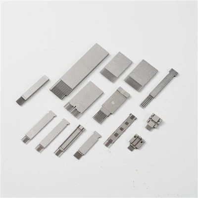
At the end of the day, calculating connector mold shot size isn’t just a math problem—it’s a combination of part-specific details, mold design, and production requirements. For connector manufacturers, getting this right avoids costly delays, material waste, and part failures that can damage your brand. If you’re currently sourcing a connector mold, or refining your existing molding process, we specialize in high-precision connector tooling with shot size calculations tailored exactly to your part and production needs. We don’t just send a quote with a mold price; we share a full breakdown of all volumes, buffer sizes, and machine capacity to ensure your parts meet every tolerance and performance requirement. Reach out to our team to discuss your project, and we’ll help you nail your shot size and get your production running smoothly.
Precision Components References
- Rosato, D. V., & Rosato, M. G. (2004). Injection Molding Handbook (5th ed.). Springer.
- International Organization for Standardization. (2018). ISO 13952: Plastics – Injection molding machines – Determination of shot size.
- Groover, M. P. (2020). Fundamentals of Modern Manufacturing: Materials, Processes, and Systems (7th ed.). John Wiley & Sons.
- American Society of Mechanical Engineers. (2019). ASME B46.1: Surface Texture – Surface Roughness, Waviness, and Lay.
Dongguan Hezong Precision Technology Co., Ltd.
With abundant experience, we are one of the most professional connector mold manufacturers and suppliers in China. Please feel free to buy durable connector mold made in China here from our factory. All customized products are with high quality and competitive price.
Address: No.973, Dalang Section of Wozhang Road, Dalang Town, Dongguan City, Guangdong Province
E-mail: postmaster@hezongjingmi.com
WebSite: https://www.hzpre.com/
